English
 日本語
 français
 Deutsch
 Español
 italiano
 русский
 português
 العربية
 Türkçe
 Polska
 Nederland
Jan 10 2023
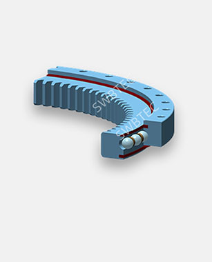
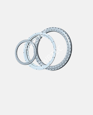
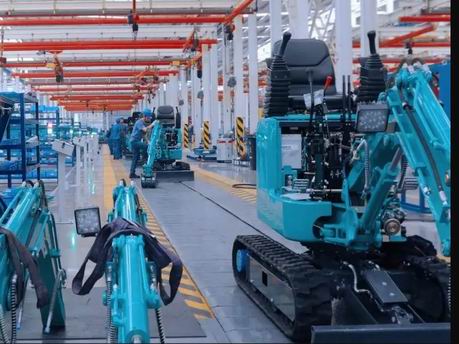
Reasons and Solutions for Leakage of the Slewing Bearing
Read More >

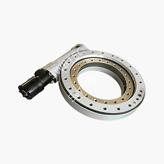
How to Select the Right Slewing Bearing for Your Equipment: A Practical Selection Guide for Engineers
Selecting a slewing bearing is not simply a matter of finding a model with roughly the right dimensions in a catalogue; rather, it involves ensuring that the slewing bearing's load-carrying capacity, structural interfaces, drive method and operating environment are all optimally matched to the equipment's actual operating conditions. If the slewing bearing is undersized, the raceways will develop indentations or spalling at an early stage; if it is oversized, unnecessary costs will be incurred in terms of weight, price and installation space; whilst neglecting the compatibility of gears, bolts or seals may result in the entire machine breaking down well before its designed service life, even if the slewing bearing itself has sufficient load-carrying capacity.
Below, we outline a practical selection approach from an engineering perspective.
I. Calculate the load accurately first, rather than looking at the model number:
Slewing rings are subjected simultaneously to axial force Fa, radial force Fr and overturning moment M. Many selection errors stem from focusing solely on the overturning moment whilst neglecting the combination of axial and radial forces, or from calculating based solely on rated operating conditions without factoring in impact loads, wind loads or braking inertial forces. For boom-type equipment, such as cranes, aerial work platforms and grab loaders, the overturning moment is often determined by the boom length and off-centre loading, whilst for excavators and bucket-wheel excavators, the controlling loads are more closely related to digging resistance and slewing braking.
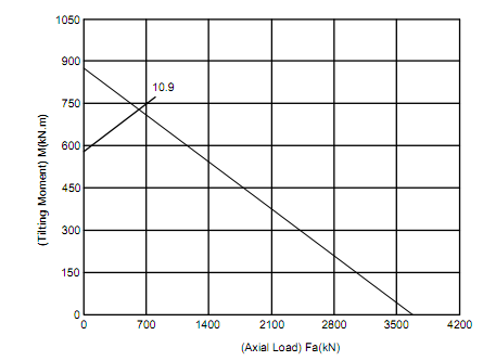
The correct approach is as follows: first, list the maximum load combinations that may occur during the entire working cycle of the equipment, including wind loads in a stationary state, overloads under test conditions, and non-operational loads generated during assembly and disassembly; then convert these to the slewing bearing centre position. On this basis, multiply by the service factor. For smooth, intermittent operating conditions, a service factor of 1.2 to 1.5 is typically used; for small to medium-sized cranes or standard excavators subject to moderate impact and load fluctuations, a factor of 1.5 to 2.0 is applied; and for mining and port equipment subject to severe impact, as well as operating conditions with uncertain dynamic loads, the service factor should range from 2.0 to 3.0. The service factor is not an arbitrary coefficient used merely to add a margin of safety, but rather a quantitative acknowledgement of the actual uncertainty in the forces acting on the equipment.
II. The selection of the structural series depends on which load is the controlling factor
The four commonly used structural series for slewing rings each have different load-bearing principles; selecting the wrong series often has more serious consequences than miscalculating a single figure.
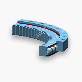
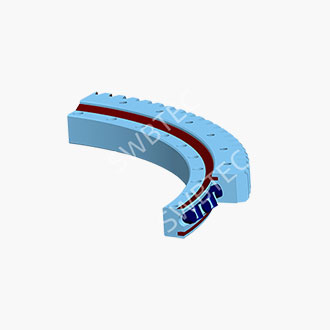
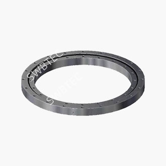
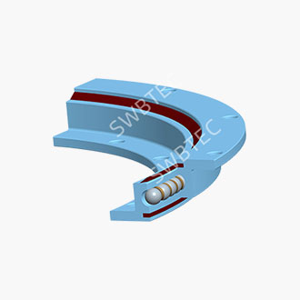
The single-row four-point contact ball type slewing bearing is the most versatile starting point. Each ball forms four contact points with the raceway; the single-row design can simultaneously withstand axial, radial and overturning moments, whilst featuring a slim profile, low dead weight and relatively controllable costs. It is suitable for small and medium-sized cranes, small excavators, photovoltaic tracking mounts and general-purpose industrial turntables. However, if the equipment is subject to significant overturning moments or severe impacts, the contact stress on the raceway of a single-row four-point contact ball bearing will rapidly approach its limit.
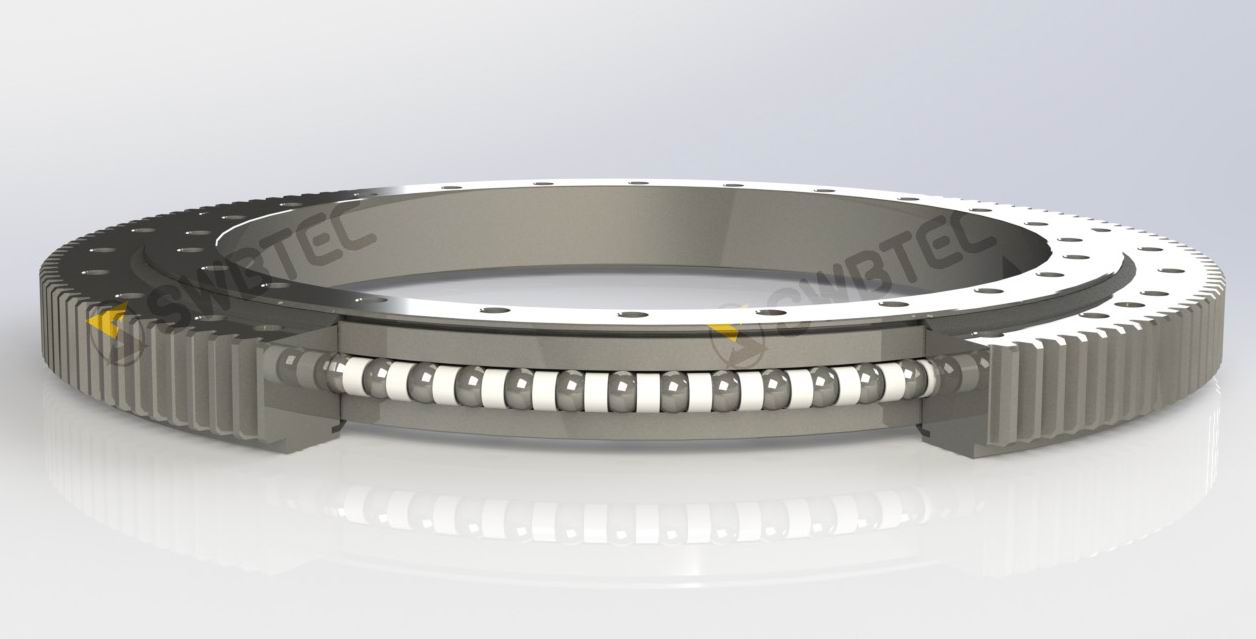
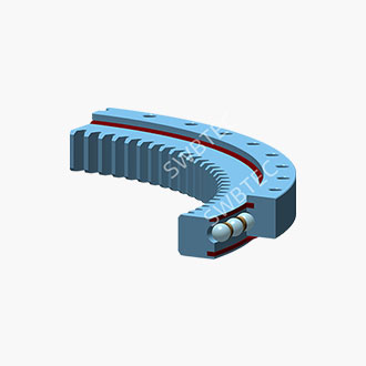
The double-row slewing ring bearings, mixed-diameter ball bearing offers a significant improvement in axial load-carrying capacity and resistance to overturning compared to the single-row ball bearing. It is suitable for equipment subjected to medium-heavy loads, bidirectional axial loads or high wind loads, such as truck-mounted cranes and certain wind turbine rotation applications.
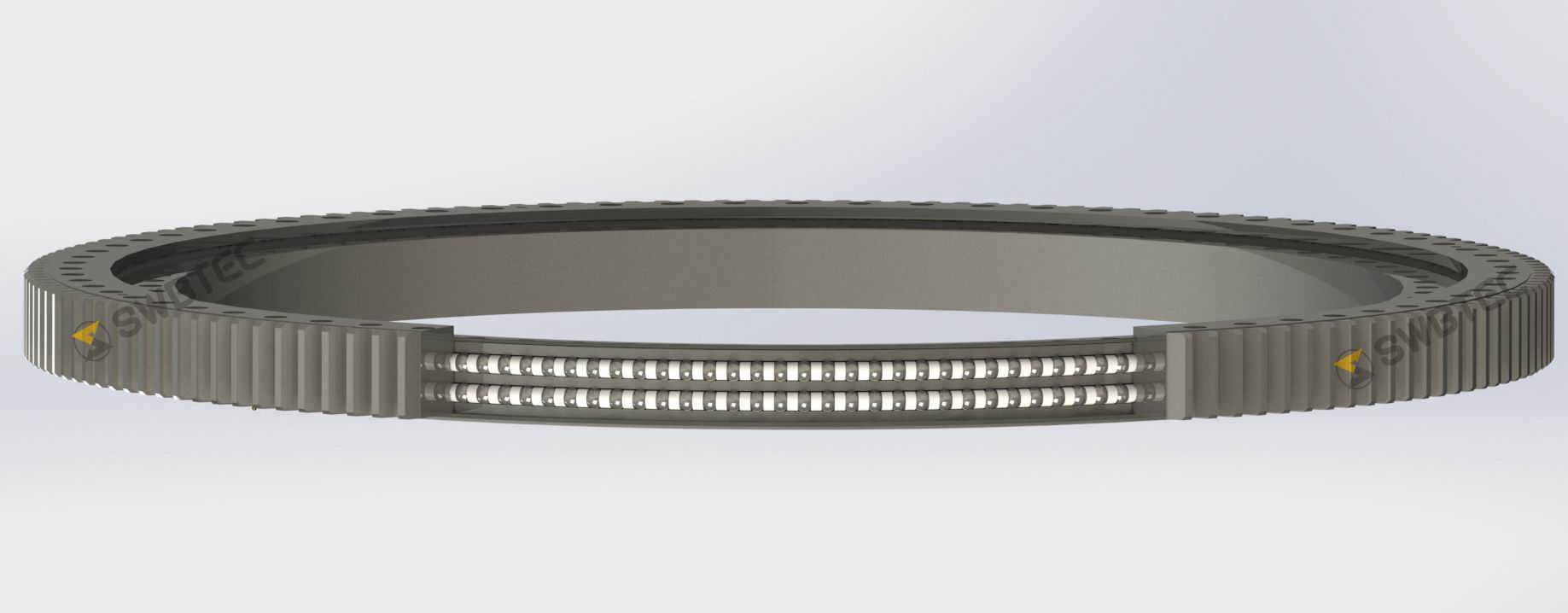
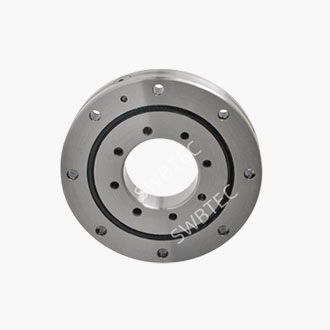
In the crossed-roller bearing, the rollers are arranged at 90° to one another, providing high rigidity and rotational accuracy, with a compact radial dimension; its load-carrying capacity is typically superior to that of ball bearings for the same outer diameter. Typical applications include radar systems, machine tool rotary tables, precision jigs and robot bases; however, the cost and requirements for installation accuracy are correspondingly higher.
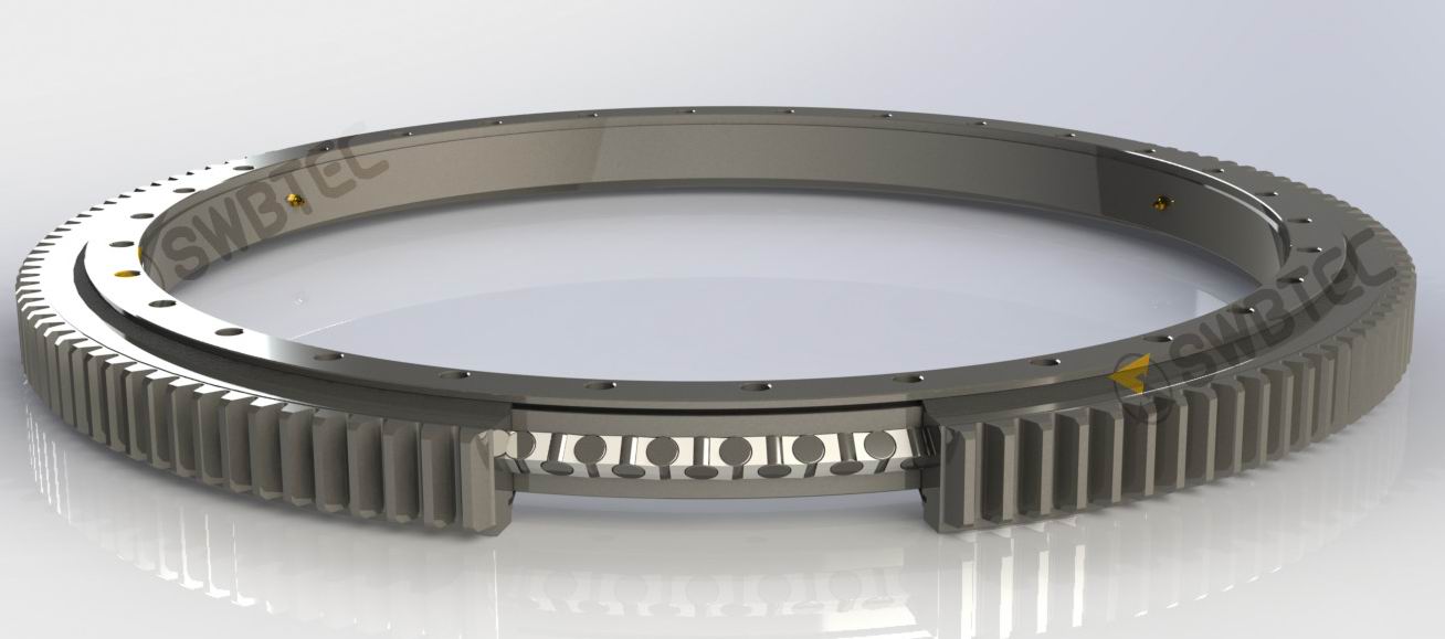
Three-row roller bearings distribute axial, radial and overturning loads across independent rows of rollers, offering the highest load-carrying capacity. They are suitable for heavy-duty truck-mounted cranes, harbour gantry cranes, bucket-wheel excavators and large metallurgical rotary tables. The trade-off is a significant increase in size, weight and installation space.
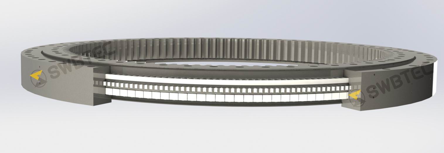
A practical approach to selection is as follows: if the overturning moment is the controlling load, priority should be given to the double-row or triple-row series; if radial loads or rigidity requirements are paramount, the cross-roller type is more suitable; if the loads are balanced and cost-effectiveness and compactness are the priorities, the single-row four-point contact ball type remains a reasonable starting point. However, the final decision must be based on verification using the load capacity curve.
III. Gears Are Not Afterthought Accessories
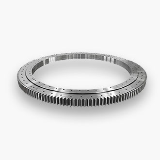
The selection of gears for toothed slewing bearings is often deferred until after the slewing bearing housing has been specified; this is a common cause of premature tooth surface wear and tooth breakage. The parameters requiring verification for gears include, at a minimum, the module, number of teeth, tooth width, tooth surface hardness and compatibility with the pinion. The tooth surfaces typically require hardening treatment; in applications subject to high impact, high-frequency or induction hardening should be employed, with hardness generally controlled within the range of HRC 50 to 60.
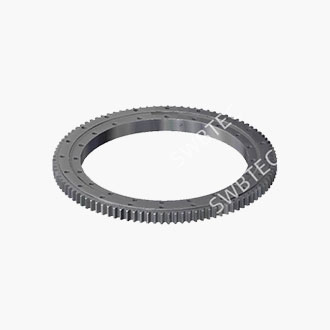
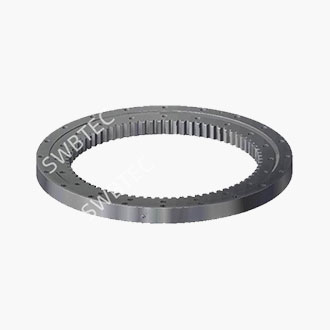
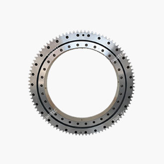
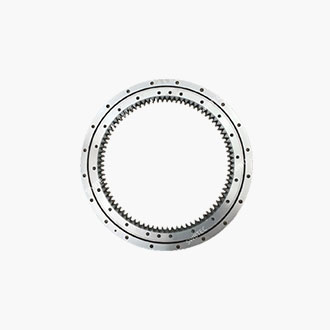
The choice between external and internal gearing should not be based solely on ease of machining. External gearing has a larger pitch circle diameter for the same module and delivers higher output torque; with the pinion mounted externally, inspection and replacement are more convenient, making it the mainstream approach in construction machinery. Internal gearing positions the ring gear within the inner ring, offering a compact structure and protection for the teeth; it is suitable for applications with space constraints or in dusty, muddy or wet environments, but involves higher machining costs and greater installation complexity. It is recommended that the number of teeth on the paired pinion be no fewer than 17 to minimise concentrated wear on the ring gear. Gear backlash must be matched to the positioning accuracy requirements: if too small, it will cause overheating and seizure; if too large, it will generate impact during direction changes.
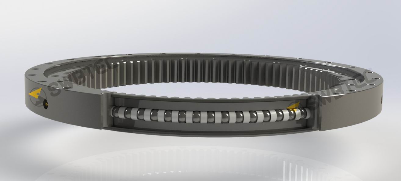
IV. The environment dictates the choice of seals, not the other way round
Seal selection is not simply a matter of any seal will do. In dry indoor environments, a single-lip seal is sufficient; outdoor conditions involving dust, mud, water or washing require double-lip seals or combination seals featuring a labyrinth with a lip; for marine, chemical or low-temperature environments, materials resistant to media and low temperatures—such as fluororubber—must be considered, along with appropriate surface anti-corrosion treatments. The choice of grease is similarly governed by rotational speed and temperature: grease lubrication is the standard solution for low-speed, heavy-load applications, whilst continuous rotation at high linear speeds requires an assessment of the feasibility of oil lubrication or centralised lubrication.
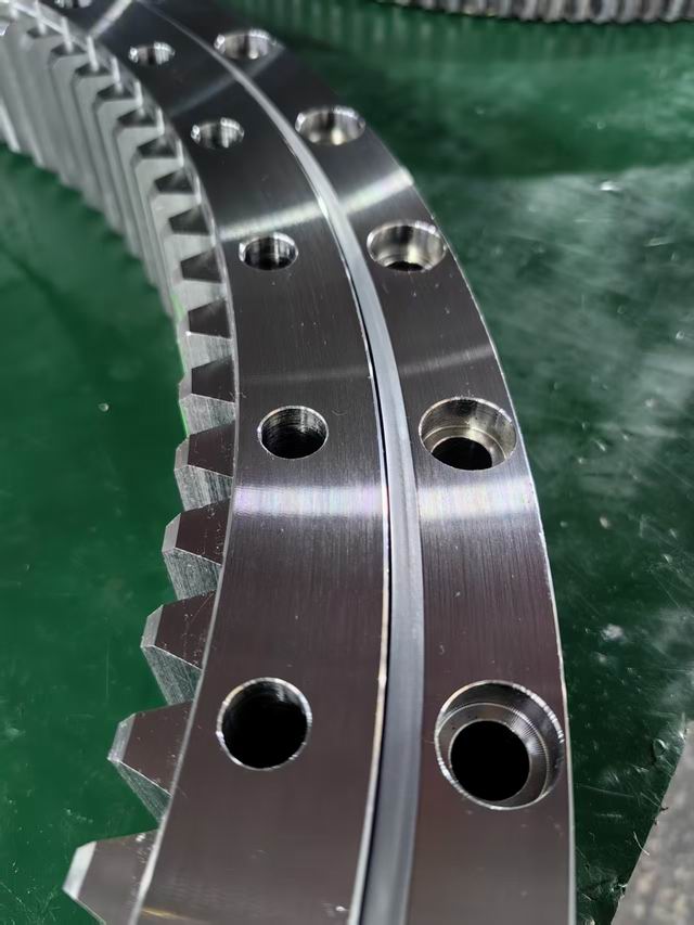
One detail that is easily overlooked is the position of the soft band in the raceway resulting from quenching. It is inevitable that a soft band will remain on the slewing bearing rings after quenching; during installation, this must be positioned in an area not subject to significant loads. If the soft band is oriented in the direction of the maximum overturning moment, the raceway will experience rapid wear long before the calculated service life is reached.
V. Mounting interfaces and bolts form part of the selection process
Many cases of premature failure attributed to slewing bearing quality actually originate from the mounting interface. The flatness of the mounting surface must typically be controlled to within required data, and welded bases must undergo stress relief treatment; insufficient rigidity in the supporting structure can lead to localised deflection under load, causing the bearing raceways to be subjected to unaccounted-for edge stresses. Bolt verification is just as important as slewing bearing verification: High-strength bolts of Grade 10.9 or higher 12.9 should be prioritised; they should be pre-tensioned in stages following a diagonal sequence, with the pre-tensioning force generally set at around 70% of the bolt's yield strength. Furthermore, the use of spring washers to compensate for insufficient pre-tensioning is prohibited. For suspended installations or structures with uneven bolt hole arrangements, the distribution of bolt loads must be calculated separately; empirical values for standard installations cannot be applied directly.
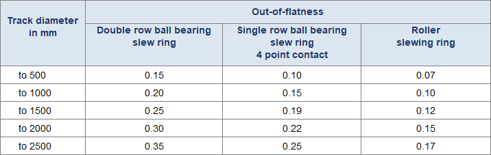
VI. Compiling a Checklist of Selection Parameters
Before contacting suppliers, organising the following information clearly can significantly shorten the technical consultation process and ensure that the supplier’s verification is based on actual data rather than assumptions: maximum Fa, Fr and M values, along with the corresponding operating conditions; rotational speed, swing angle and number of cycles; inner and outer diameter and height constraints of the installation space; drive type (internal gearing, external gearing or gearless) and gear parameter requirements; operating temperature, dust, moisture, salt spray and other environmental conditions; accuracy grade and clearance requirements; mounting surface rigidity and bolt layout. Only by presenting this checklist during discussions will suppliers be able to provide reliable recommendations that fall within the load capacity curve, rather than merely guessing a model based on diameter alone.
Frequently Asked Questions (FAQ)
Q: When selecting a slewing bearing, is it sufficient to consider only the overturning moment?
No, it is not sufficient. Whilst the overturning moment is often the controlling load in boom-type equipment, axial and radial forces must also be factored into the load capacity curve verification. Selecting a model based solely on the overturning moment may result in a model where the diameter appears adequate, but the actual contact stress on the raceway has already exceeded the limit. The correct approach is to multiply the combination of Fa, Fr and M by the service factor, and then plot these values on both the static and dynamic load capacity curves.
Q: Is a safety factor of 1.5 sufficient to ensure safety?
It depends on the operating conditions. A factor of 1.5 is suitable for steady, intermittent operation with well-defined loads and minimal impact. Small and medium-sized cranes and standard excavators typically require a factor of 1.5 to 2.0; for mining, port operations, heavy-duty boom equipment and applications with uncertain dynamic loads, a factor of 2.0 to 3.0 should be used. Hiding impact loads behind an unduly low safety factor is a common cause of premature indentation in raceways.
Q: When must a cross-roller bearing be selected over a single-row four-point contact ball bearing?
When equipment has specific requirements for rotational rigidity, positioning accuracy or radial load-carrying capacity, a cross-roller bearing is usually the more suitable choice. Its crossed roller arrangement provides higher rigidity and lower clearance, making it suitable for robot joints, precision turntables and radar mounts. If the equipment is a general-purpose lifting or slewing support, where loads are predominantly axial and overturning, single-row four-point contact ball bearings offer greater advantages in terms of cost and space.
Q: Do the gears of a toothed slewing bearing need to be verified together with the slewing bearing?
Yes. The module, tooth width and tooth surface hardness of the gear must be matched to the torque to be transmitted, and the quality of the tooth surface hardening directly determines the service life of the gear ring. If the bearing is selected first and the gear matched afterwards, a situation may arise where the bearing has sufficient load-carrying capacity but the contact stress on the tooth surface is excessively high. Addressing the gear parameters alongside the bearing load in a single verification process can avoid this oversight.
Q: Does the strength of the mounting bolts really affect the service life of a slewing bearing?
Yes, it does. If the bolts are insufficiently preloaded or do not meet the required strength grade, the working load will repeatedly act on the bolted connection, causing the preload to relax and resulting in relative micro-movement of the bearing mounting surfaces, which in turn alters the force distribution on the raceways. In many cases, the root cause of on-site failures lies with the bolts, rather than the raceways themselves. Bolt verification should be carried out simultaneously with the slewing bearing load verification.
Q: When replacing a slewing bearing in old equipment, can we simply purchase the same model as before?
It is not advisable to simply replicate the original model. The original model merely indicates that the geometric interfaces were once compatible; it does not guarantee that the original selection was adequate. If the old slewing bearing has suffered premature failure, it is even more important to re-examine the actual load, service factor, seal condition and mounting surface rigidity to determine whether the failure was caused by an undersized bearing, environmental ingress or installation deformation. Replacing the slewing bearing with the original model risks replicating the same problem.
Ultimately, the selection process amounts to a re-evaluation of the system's compatibility: loads, structure, gearing, seals and mounting interfaces. If any of these elements is treated as a secondary consideration, deemed good enough, it will inevitably become apparent during the equipment's actual service life.
The engineering expertise SWBTEC has accumulated in the manufacture and supply of slewing bearings centres precisely on these interface issues. If you are seeking to match a suitable slewing bearing to a specific piece of equipment, or if you have a load list that requires verification, please feel free to send us the operating conditions. Our technical team will work with you to ensure the selection aligns with the load capacity curve, rather than remaining confined to the dimensional tables in a catalogue.