English
  日本語
日本語  français
  Deutsch
  Español
  italiano
  русский
  português
  العربية
  Türkçe
  Polska
  Nederland
Aug 23 2023
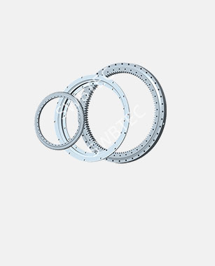
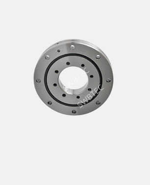
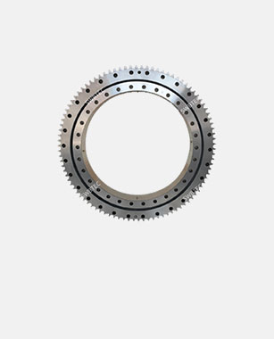
Incorporating Slewing Bearings with External Gear to Enhance Safety and Performance in Cranes and Lifts
Read More >


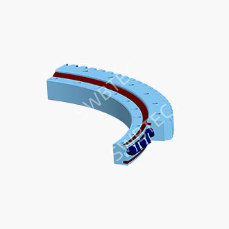
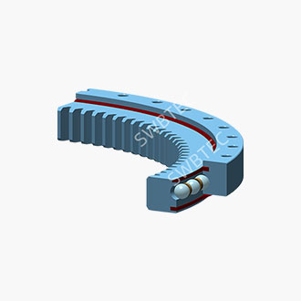
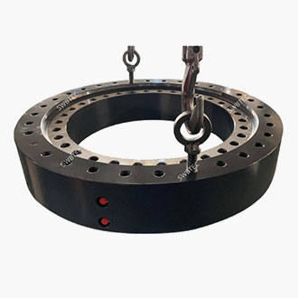
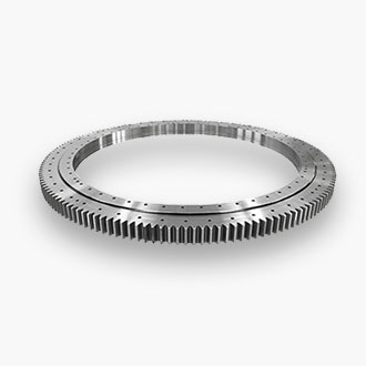
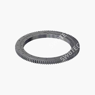
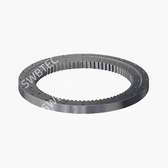
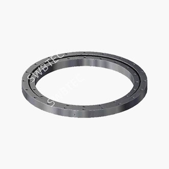
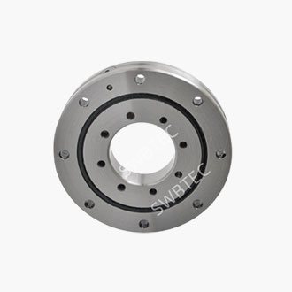
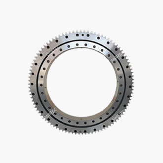
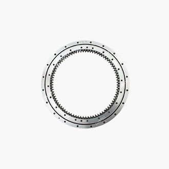
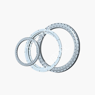
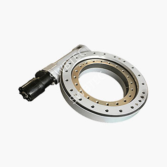
Double-row ball-type slewing bearings for truck-mounted cranes: how to optimise the load distribution curve whilst balancing heavy loads and long-boom operating conditions
Different applications require different slewing bearing designs. The most challenging operating conditions for truck-mounted cranes are not simply lifting heavy loads, nor simply extending the boom to its full length, but rather the simultaneous occurrence of both. The longer the boom, the greater the overturning moment generated by the load; the heavier the load, the higher the contact stress on the slewing bearing raceways. For double-row ball-type slewing bearings, the true test lies not in the rated static load capacity figure, but in how the load is actually distributed across the upper and lower rows of balls and the circumferential contact points under composite moments. For small- to medium-tonnage truck-mounted cranes, SWBTEC's double-row ball-type structure is straightforward: one inner ring, one outer ring, and two rows of balls of the same diameter. This structure has its advantages, but it also presents distribution challenges that must be addressed.
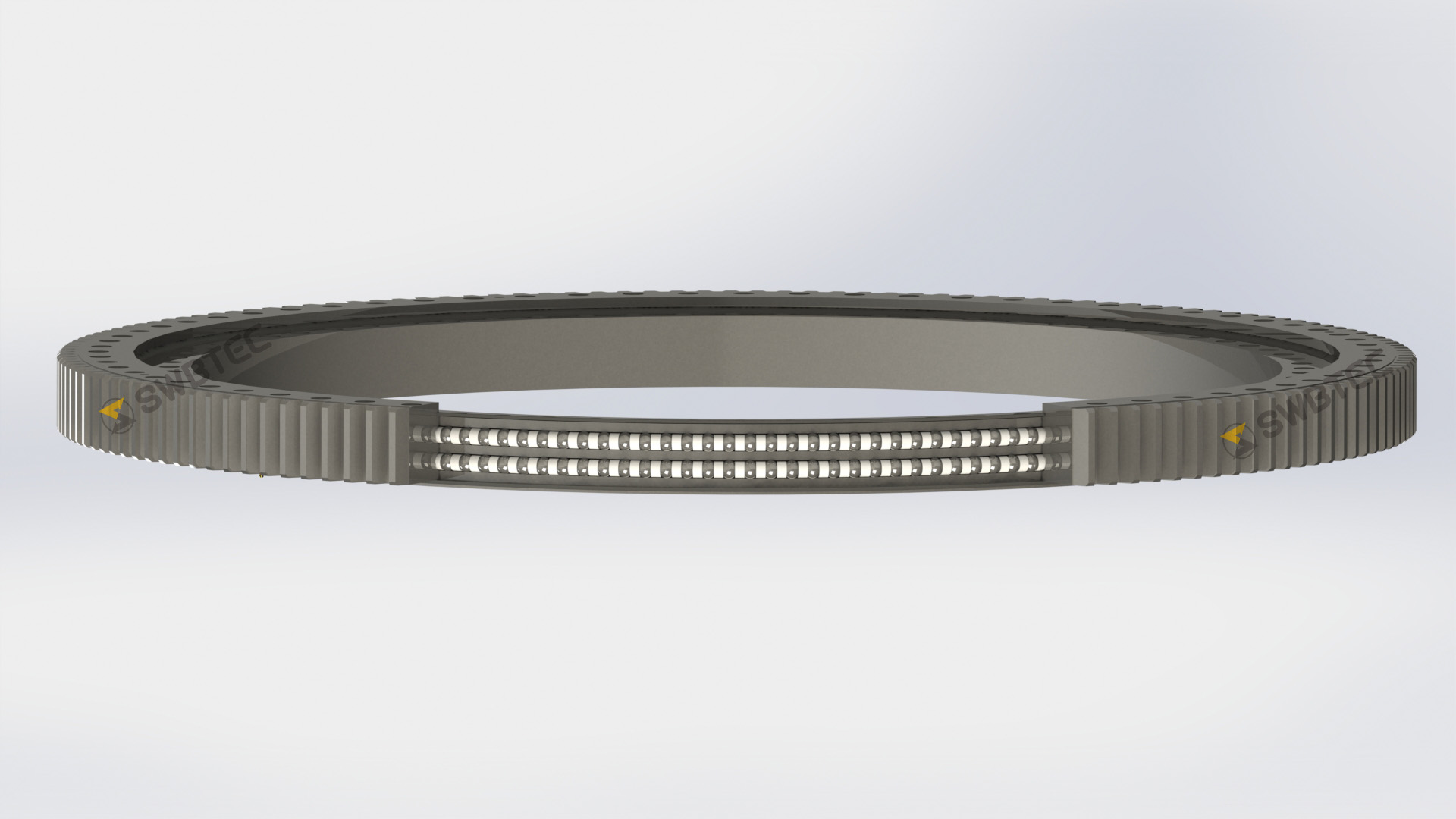
I. Understanding the structure: a single inner ring, a single outer ring, and two rows of steel balls of the same diameter
The basic logic of load distribution
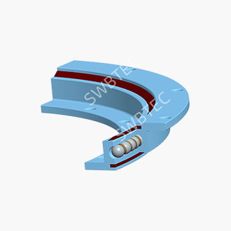
SWBTEC's double-row ball slewing rings utilise a single inner ring and a single outer ring, with two upper and two lower raceways on the outer circumference of the inner ring and the inner circumference of the outer ring respectively; the upper and lower rows of steel balls are of the same diameter. Each ball forms four points of contact with both the inner and outer rings. Under purely axial forces, the upper and lower rows of balls bear the load in the same direction, which in theory can be distributed relatively evenly; radial forces are borne by the horizontal component of the contact angle; whilst overturning moments cause the rings to tilt relative to one another, with one side of the upper row being compressed and the opposite side of the lower row being compressed, forming a pair of force couples. In other words, the overturning moment does not exert pressure on a single row in isolation, but rather causes the upper and lower rows to redistribute the load diagonally.
Design constraints arising from identical ball diameters
The fact that the upper and lower rows of balls have the same diameter means that their contact stiffness, contact ellipses and load-carrying capacity are essentially symmetrical. The advantages are a simple structure, stable assembly processes, and the absence of sudden changes in stiffness between the rows caused by differences in ball diameter. Conversely, however, unlike structures with balls of different diameters, it is not possible to artificially bias the load-carrying capacity by using ‘larger balls in the upper row and smaller balls in the lower row’. To optimise the load distribution curve, one must focus on the raceway profile, contact angle, curvature ratio, consistency of clearance and installation stiffness. This is also why, even though they are both referred to as double-row ball slewing bearings, there can be significant differences in their actual service life.
II. What exactly does the load distribution curve describe under long-boom operating conditions?
Put simply, the load distribution curve illustrates how the load varies circumferentially along the raceway and how it is distributed between the upper and lower rows when a combination of axial forces, radial forces and overturning moments acts upon the bearing. When the boom of a mobile crane is fully extended, the overturning moment accounts for a significant proportion of the total load. The load curve is no longer uniformly distributed around the circumference but exhibits a distinct 'high on one side, low on the other' pattern. If the design is inadequate, high-stress zones will concentrate on a small number of balls, leading to premature indentations or spalling in localised areas of the raceway.
The optimisation objective is not to achieve a completely uniform load distribution—which is unfeasible under actual operating conditions—but rather to smooth out the peaks: to ensure that more balls participate in load-bearing, to create a gentler transition between the contact zones of the upper and lower rows, and to prevent the contact stress gradient from becoming too steep. For double-row ball bearing structures of the same diameter, this relies particularly on the consistency of the raceway geometry and the assembly condition.
III. Several Key Focus Areas for Optimising the Load Distribution Curve
1. Profile of the raceways and spherical profiling of the upper and lower rows
Where the upper and lower rows consist of balls of the same diameter, if the profiles of the upper and lower raceways of the inner ring and those of the outer ring do not form a common spherical surface, the contact angles at the same axial cross-section will be inconsistent. The result is that, when a overturning moment acts, one row makes contact and bears the load first, whilst the other row does not contribute sufficiently. During optimisation, it is essential to ensure that the upper and lower raceways of both the inner and outer rings form a unified centre-of-sphere relationship during grouped machining, so that the contact angles of the balls in the same row are consistent and symmetrical between the upper and lower rows. For long-arm operating conditions, slight profiling of the main load-bearing sector may also be applied to avoid stress concentration at the raceway edges.
2. Matching the Contact Angle and Curvature Ratio
The contact angle determines the ratio in which the ball distributes the force between the axial and radial directions. If the contact angle is too small, the axial load-bearing component is insufficient; if it is too large, the radial component is compressed, and the contact ellipse tends to shift towards the edge of the raceway. The curvature ratio is equally critical: if the ratio of the raceway radius of curvature to the ball radius is too small, the contact ellipse becomes small and stresses increase; if too large, contact stiffness decreases and deformation increases. For composite operating conditions such as those encountered in mobile cranes, which require both high load-carrying capacity and a long jib, the contact angle and curvature ratio cannot be selected directly from general selection tables; calculations must be based on the specific load ratio.
3. Consistency between Upper and Lower Row Clearances and Preload
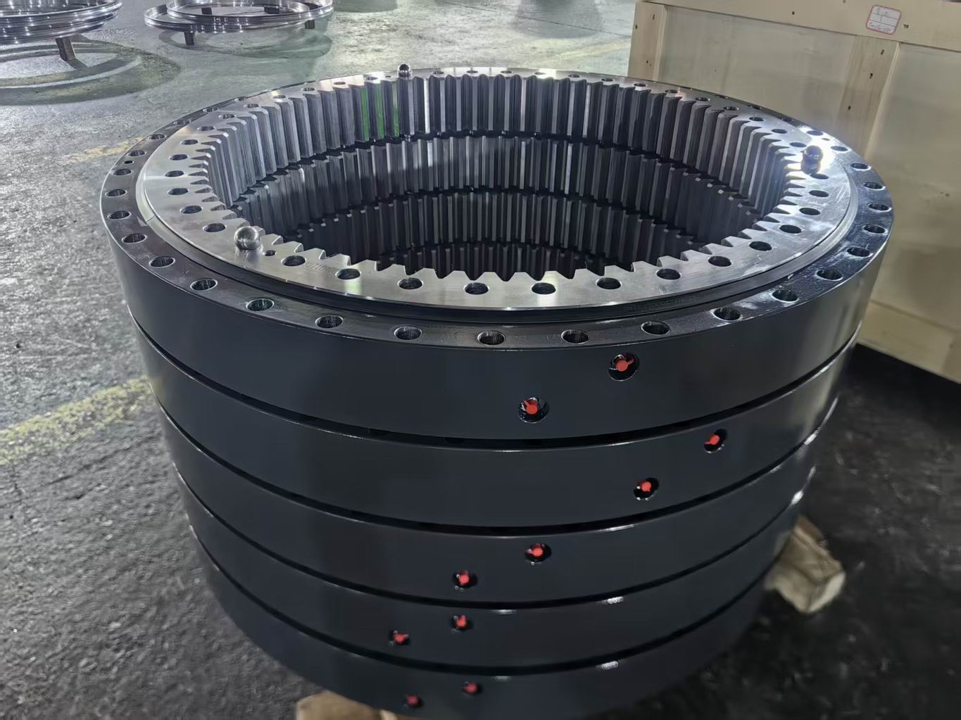
In same-diameter ball bearing structures, the difference in clearance between the upper and lower rows is the most easily overlooked factor leading to failure. In theory, the upper and lower rows are symmetrical; however, if, after assembly, the upper row has minimal clearance whilst the lower row has excessive clearance, the upper row will bear the load first under overturning moments, whilst the lower row will be slow to contribute. Consequently, the nominal dual-row load-bearing configuration degenerates into a single-row dominant arrangement. During the assembly process, SWBTEC implements paired control of the contact conditions between the upper and lower rows, rather than merely checking whether the total clearance meets the specified standard. For high-frequency, heavy-duty equipment such as mobile cranes, clearance consistency directly determines whether the load distribution curve approximates the design value.
4. Installation Stiffness and Bolt Preload
A slewing bearing does not operate in isolation. It is connected between the turntable and the chassis via bolts; local deformation of the turntable base plate under off-centre loading alters the distribution of bolt tension, which in turn changes the pressure distribution on the raceways. It is frequently observed in finite element analysis that, under conditions of significant off-centre loading, local deformation of the base plate causes the load to concentrate on a small portion of the raceway. To optimise the load distribution curve, one must not only modify the slewing bearing itself but also pay attention to the flatness of the mounting surface, bolt preload and the matching of connection stiffness.
5. Position of Ball-Plugging Holes and Raceway Continuity
Double-row ball-type slewing bearings require ball-stop holes during assembly. If these holes are located within the primary load-bearing zone, the continuity of the raceway is disrupted, making this area a likely fatigue initiation point. For heavy-load conditions on the long boom of a mobile crane, ball-stop holes should, as far as possible, be avoided in the high-stress sectors subjected to overturning moments. Whilst this detail may seem minor, many cases of early spalling failure can be traced back to problems originating near the ball-stop holes.
6. Consistency in Heat Treatment and Machining
Induction hardening of the raceways must ensure uniform hardness and depth of the hardened layer. The material commonly used is 42CrMo, whilst 50Mn is rarely employed. The surface hardness of the raceways is typically required to be 55–62 HRC, and the depth of the hardened layer must be sufficient and consistent, without fluctuating in depth. Uneven hardness will cause fluctuations in contact fatigue life; insufficient machining accuracy of the profile means that the load distribution curve optimised through simulation cannot be realised in the actual product. The double-row ball bearing structure with identical ball diameters places even higher demands on the consistency of the upper and lower raceways, as there is no difference in ball diameter to 'mask' machining deviations.
IV. From Simulation to Vehicle Loading: A Pragmatic Optimisation Process
Step 1: Establish a realistic load spectrum. Do not focus solely on the maximum lifting capacity; ensure that operating conditions such as medium loads with long booms, heavy loads with short booms, boom swing under load, and sudden unloading are all included.
Step 2: Use a finite element model to identify high-stress sectors. Determine which side of the upper row compresses first under overturning moments, which side of the lower row is underutilised, and at which angle contact stress peaks occur.
Step 3: Fine-tune the raceway profile, contact angle and curvature ratio for high-stress areas. Prioritise resolving uneven load distribution between the upper and lower rows, followed by addressing circumferential stress peaks.
Step 4: Finalise key parameters for the manufacturing stage. Process control must encompass raceway profile inspection, hardened layer depth, clearance matching between the upper and lower rows, and the positioning of the ball-seating holes.
Step 5: Monitor actual operating conditions following installation on the vehicle. No matter how impressive the theoretical curves may be, they must be refined based on feedback from actual use.
V. FAQ – Frequently Asked Questions
Q: What is the structure of your double-row ball slewing bearing?
SWBTEC employs one inner ring and one outer ring, with upper and lower rows of steel balls of the same diameter. It does not feature a centre ring structure, nor does it utilise balls of different diameters in the upper and lower rows. As the steel balls in both rows are of the same diameter, the contact stiffness and load-carrying capacity are symmetrical.
Q: In a structure with balls of the same diameter, how is the load distributed between the upper and lower rows under a tilting moment?
Under pure axial force, the upper and lower rows share the load in the same direction; under a tilting moment, one side of the upper row and the opposite side of the lower row form a force couple, with one side being compressed and the other released. The fact that the balls are of the same diameter means that the theoretical stiffness of the upper and lower rows is identical; the actual load distribution depends primarily on the raceway profile, contact angle, consistency of clearance and installation stiffness.
Q: To optimise the load distribution curve, is it simply a matter of increasing the contact angle?
No. Increasing the contact angle does increase the axial load-bearing component, but it also affects the radial load-bearing capacity and the position of the contact ellipse. If the contact angle exceeds a certain range, the contact stress actually concentrates towards the edges of the raceway. Selection must be based on the specific load ratio.
Q: If the upper and lower rows have the same diameter, can load distribution be improved through assembly?
Yes, and this is crucial. If the clearance between the upper and lower rows is inconsistent, even in a same-diameter configuration, one row may make contact first whilst the other joins later. During assembly, the contact status of the upper and lower rows must be controlled in pairs; one must not rely solely on the total clearance.
Q: Does the stiffness of the mounting base plate really affect the service life of the slewing bearing?
Yes. Deformation of the turntable base plate under off-centre loading alters the bolt preload and the pressure distribution on the raceways. Under conditions of significant off-centre loading, insufficient base plate rigidity can cause the load to concentrate on a small portion of the raceway. The slewing bearing and its mounting structure must be considered together.
Q: Why is the position of the ball-stop holes important?
Ball-stop holes interrupt the continuity of the raceway. If they fall within the primary load-bearing zone, they can easily lead to stress concentration and become fatigue initiation points. During design, the ball plug holes should be positioned outside the high-stress sectors.
Q: What support can SWBTEC provide?
Based on the specific load spectrum of a truck-mounted crane, we can perform load distribution simulations, selection calculations and customised designs for double-row ball-type slewing bearings, helping original equipment manufacturers (OEMs) find a more suitable balance between heavy-load capacity and long-boom operating conditions.
If you are selecting a slewing bearing for a new generation of truck-mounted cranes, or wish to conduct a systematic assessment of the load distribution of your existing double-row ball slewing bearings, please feel free to contact SWBTEC. we will provide technical feedback within one working days.